
I've had a car charger break down on me and haven't been able to fix it. It has a sturdy metallic case and the transformer is still fine.
The idea is to use some existing PSU modules I have laying around and fit those into the case, providing a readout on the display. Since it has to have a microcontroller (overpowered if I might add) it can also do some basic logging, over-voltage and over-current protection.
I really hate designing my own supplies since there are so many ready-made around which are much better than I could ever accomplish.
Bill of materials:
- case with transformer
- LM2596 module (sells for around 2.5$ on ebay)
- L4964 module (got it for free, it's probably around 10-15$)
- Stellaris Launchpad (got mine for 5$, now selling for 12$)
- Nokia 3110/5110 display (got mine for around 3$ with breakout headers)
- assortment of resistors and wires
LM2596
 The module is supposed to be capable of supplying 2.5-3A but I found it got really hot at everything more than 1.5 amperes. The supplied variable resistor has to go since it can only be operated with a fine screwdriver.
Output voltage should go from 1.2V to 30V.
L4964
This is supposed to be the beefy supply that will power my hungry projects and charge car batteries and such. It can do 5.1-30V at 4 Amps.
Stellaris Launchpad
I'm using the Energia framework since it's much faster to develop on then on the TI dev chain.
Eight of the 40 available pins are used for the display, 2 are coming from the voltage outputs of the two modules and another 2 are coming from each of the low-side shunt resistors to provide current reading.
In the future, two additional pins will be used to shutdown the power supplies for protection and another bunch of pins will connect to an SPI RF module. That's part of the 'Connected Workbench' project and will have a post series themselves..


Since the display has only 84x48 pixels resolution we don't have a lot of space to work with, so the readouts will have to be split into several screens.
The first image shows the general readout, with the two power supplies' voltages and currents. If you look very carefully below the voltage numbers you will see a small 1-pixel "analog" graph.
Another screen will provide basic datalogging since the supply could also technically be used with its outputs turned off. The picture on the left exemplifies this with the temperature.
The graph auto-scales between the minimum and maximum recorded values, displaying them as well.
Look at the bottom of this posting example for source code.
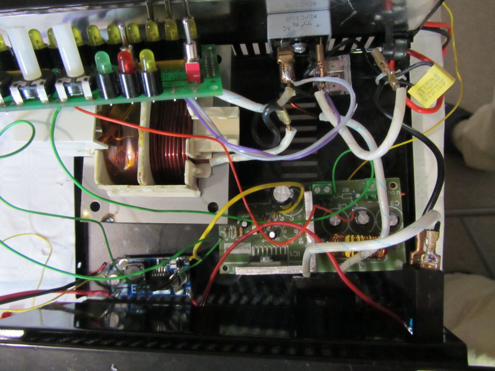
Wiring
The transformer can supply 40Vpp which translates into about 21V after a bridge rectification. The L4964 module has its own rectification module, but everything translates into the fact that my setup cannot go over 20V output voltages.The StellarPad is running at 3.3V so any input to it must be lower than that. This includes the voltage dividers set up on the PSU outputs AND the size of the shunt resistors.

Regarding the shunt resistors, initially I calculated that I will not exceed 17V/3A so a 0.56 ohm 3-Watt resistor should suffice. However, in testing, I connected a small battery that was feeding current back into the voltage supply and that current rose to ~7A for a brief period of time, causing the StellarPad to go crazy for about an hour afterwards.
Continuous testing also showed that at 1.5-2A the resistors would get too hot to touch and the output voltage dropped significantly. So I wired two of the resistors in parallel yielding 0.28 ohms. I haven't tested this new configuration but it should suffice for my needs.
I wrote above about the problem with voltage on the inputs of the uC exceeding maximum ratings. I've done this before with Microchip PICs and never had any issue if performed for short periods of time. To protect the chip against these peaks I wired an LED in parallel with the shunt. The LED was already there on the prototyping board I used so it will provide a nice overcurrent light as well.
If you are wondering how this works: the LED has a drop voltage of 1.7-1.8V so any voltage higher than this across it will cause it to light up and will be drained through the LED, limiting the voltage across the shunt (and into the chip) at 1.8V.
If you are wondering how this works: the LED has a drop voltage of 1.7-1.8V so any voltage higher than this across it will cause it to light up and will be drained through the LED, limiting the voltage across the shunt (and into the chip) at 1.8V.
[schematic will go here if I remember to digitize it]
I had a prototyping board laying around that has three pots, more than 12 leds (with resistors) and a few switches. It seems like the perfect match for this. However, the potentiometers are 5k and the supplies required 10k and 25k for setting the voltages. So, I built an Excel sheet that allowed me to play with various resistor configurations to get the required range. Since I was not going to exceed 21V I could make the most out of the pot range within my useful voltage range.

Noise

5 times/s would prove fast, but still readable, so this was my goal.
I was aiming for a resolution of 1mV and 1mA but this is probably well below the noise floor of the chip. Nevertheless, it's nice to have those extra digits in there and perhaps with some averaging I might squeeze a few ADC bits of accuracy.
However, displaying those values proved to be a challenge as both PSUs are switch-mode and come with inherent noise. This means that the output has to be averaged in order for us humans to read it. Without this, the numbers were a blur as you can see in the top picture.
After playing around with microcontroller code for too long I decided to build an Excel file that will show me how various filters will perform. I was previously doing the "LPF 1p" implementation (low-pass filter, 1-pole) but it seems that the weighted average will give the smoothest results.
Regarding LPF, I found out that for large swings the display tracked the voltages faithfully but it took an infinite time to settle for lower changes. That is, going from 4.8V to 5V meant that a lot of the time the display was stuck at 4.95V.

Random pics


Attachments and temporary ending
The part that I dread most is achieving the end look: cutting out the front of the metal case to make room for the display and buttons, fiddling with positioning, trimming all the measurements for calibration purposes.
https://sites.google.com/site/ligius/pot%20calculation.ods?attredirects=0&d=1
https://sites.google.com/site/ligius/stellarispsu.ino.test1?attredirects=0&d=1
https://docs.google.com/viewer?a=v&pid=sites&srcid=ZGVmYXVsdGRvbWFpbnxsaWdpdXN8Z3g6MzdiYWEwYmJkMDU5NGIxNg
No comments:
Post a Comment